

Blog
Rocker Switch Basics, Fault Analysis, Solutions and Differentiations

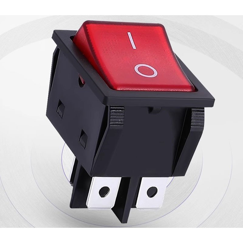
Rocker switches, also commonly known as boat switches, are one of the most widely used electromechanical switching components in commercial equipment, household appliances, and industrial devices. Many users and equipment manufacturers only understand their basic on-off functions but lack in-depth knowledge of their working principles, structural characteristics, fault maintenance, and product differentiation. This article comprehensively introduces the basic knowledge of rocker switches, analyzes common faults and corresponding solutions, summarizes effective preventive measures, and compares the core differences between rocker switches and push button switches, helping users select and use rocker switches correctly and avoid equipment failure risks.
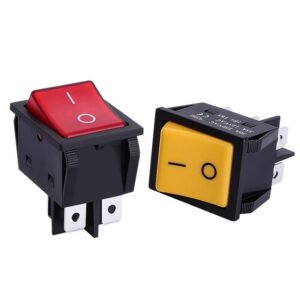
1. Basic Knowledge of Rocker Switches
A rocker switch controls circuit connection and disconnection by alternately pressing the two ends of the rocker operating button. It is mainly applied to switch on and off the main power of various electrical equipment. The swinging up-and-down operating motion of the button is the origin of the name “rocker switch”. With simple operation, intuitive status display and stable performance, rocker switches have become a mainstream power switch solution for various electrical products.
Rocker switches feature diverse product classifications, categorized by rated current, circuit number, overall dimension, and functional design. The product lineup includes conventional ordinary models, sealed waterproof models, and self-reset functional models to adapt to complex application scenarios. In general, traditional rocker switches have a larger outer size and support higher on-off current values. With continuous upgrading of manufacturing technology and internal switch mechanism optimization by manufacturers, miniaturized high-current rocker switches have been successfully developed, solving the pain point of large size and single specification of traditional products.
The operating status of rocker switches can be judged intuitively through the button state, which effectively avoids misoperation and potential equipment faults. According to the upper limit of rated breaking and closing current, mainstream rocker switches on the market are divided into three specifications: 10A, 16A, and 20A, with external dimensions varying according to current parameters.
In terms of panel mounting protruding size, 10A and conventional 16A rocker switches adopt a compact 15mm×21mm structure. Traditional 16A products used 25mm×32mm dimensions, while optimized upgraded 16A models support 17mm×24mm miniaturized size. The 20A high-current rocker switch adopts a larger 27mm×37mm structural design to meet high-load power supply demands. In addition, customized functional models are available, including dual-button control switches, illuminated indicator rocker switches, and external signal automatic reset rocker switches, covering diversified market demands.
1.1 Can Rocker Switches Be Soldered on PCB Boards?
Most conventional rocker switches are designed for panel mounting and are usually installed on equipment operation panels instead of directly arranged on PCB boards. The internal structure of the rocker switch is equipped with a central plastic partition, which effectively prevents short circuit faults caused by line swinging and frequent switch opening and closing. The four plastic clamping buckles on the switch shell enable quick installation — users only need to open square holes of matching size on the equipment panel to complete fixed assembly, with simple and efficient installation.
For special customized scenarios that require PCB mounting, rocker switches can also adapt to PCB installation requirements. It is only necessary to reserve matching slots on the PCB board according to the switch structural dimension drawing. Consistent with other plug-in electronic components, the switch terminals can be wired and matched with PCB circuits. As a typical electromechanical component, the installation mode of the rocker switch is flexible and adjustable, which can meet the structural design requirements of engineers for different equipment.
2. Core Differences Between Rocker Switches and Push Button Switches
Most users only distinguish rocker switches and push button switches by their appearance, ignoring the essential differences in safety performance, structural stability, and application limitations. These core differences determine their applicable scenarios and service life, which are key factors for equipment manufacturers to select switches.
2.1 Different Damage Ranges and Structural Stability
Affected by mechanical torque, rocker switches have a larger structural movement range during switching. In contrast, if push button switches want to achieve the same breaking stroke, their internal springs need to bear greater torsion pressure. Long-term high-torsion operation easily causes spring fatigue, deformation and failure. The common jamming and unresponsive faults of push button switches are mostly caused by the end of the internal spring service life. Rocker switches have more reasonable mechanical structure and uniform stress, effectively reducing structural damage and jamming failures.
2.2 Different Circuit Connection Limitations and Heat Dissipation Risks
Push button switches occupy a small panel space, so many brands design multi-bit specifications, with a maximum of 6-bit control. A 6-bit dual-control push button switch will be equipped with up to 12 internal wires, resulting in dense wiring inside the equipment junction box. Dense wires will cause poor heat dissipation, and long-term heat accumulation easily leads to wire aging, circuit breakage, short circuits and electric leakage accidents. Rocker switches are mostly designed with 1-3 bits, with limited internal wiring quantity, which reserves sufficient heat dissipation space for the junction box and greatly reduces hidden dangers of circuit failure.
2.3 Different Electric Leakage Risk Coefficients
The button size of conventional push button switches matches the finger width. In humid environments such as bathrooms and kitchen equipment, wet fingers will directly contact the gaps between push buttons and the panel. For low-quality switches with poor sealing performance, moisture will invade the interior, causing conductive parts to be damp and trigger electric leakage, bringing safety risks to users. The operating area and gap spacing of rocker switches are larger, which avoids direct contact between wet hands and internal conductive structures, effectively reducing electric leakage risks in humid working environments.
3. Common Rocker Switch Faults, Causes and Solutions
After long-term use or improper operation, rocker switches may experience faults such as failure to close, unresponsive switching and poor contact. The most common fault is that the rocker switch cannot be turned off normally. This chapter analyzes the root causes of faults and provides targeted repair solutions.
The interior of a rocker switch consists of metal conductive parts and elastic spring structures. Long-term use will cause spring displacement, aging and deformation of plastic support parts, resulting in inflexible switch operation and failure to reset and close normally. When this fault occurs, first cut off the equipment power supply for safety inspection. If the internal plastic structural parts are not damaged, the spring and movable parts can be manually reset to restore normal switch operation.
If the fault persists after reset, it is usually caused by damage and isolation failure of the switch neutral line. Users can cut off the damaged wiring part, rewire and do insulation protection to solve the circuit failure problem. In case of short circuit at the bottom of the switch indicator light, re-connect the internal circuit and clean up short-circuit impurities to restore the normal on-off function of the rocker switch.
4. Effective Prevention Measures for Rocker Switch Faults
Most rocker switch faults are caused by inappropriate installation environment, irregular use and mismatched specifications. Standardized use and scientific maintenance can effectively extend the service life of the switch and reduce failure probability. The key preventive measures are summarized as follows:
4.1 Avoid Humid Installation Environment
Do not install or use rocker switches in long-term humid environments. Moisture invasion will cause internal metal parts oxidation, spring rust and circuit short circuit, leading to switch failure. For equipment used in humid scenarios, it is necessary to install supporting splash-proof and waterproof covers to isolate moisture and protect internal switch structures.
4.2 Stay Away From High-Temperature Working Conditions
Long-term high-temperature operation will cause electric arcs and heat accumulation inside the rocker switch, which will trigger safety hazards such as spontaneous combustion and component burnout. It is necessary to avoid placing the switch in high-temperature equipment working areas. During installation and wiring, avoid touching conductive connection points with bare hands to prevent electric shock accidents and ensure operational safety.
4.3 Prohibit Long-Term Overload Operation
Strictly follow the rated current and voltage parameters of the rocker switch, and do not use it in overload circuits. Long-term over-current operation will exceed the load capacity of the switch contact parts, causing contact burnout and permanent failure. Set reasonable current and voltage limits during equipment installation to ensure the switch works within the rated parameter range.
4.4 Match Switch Specifications Reasonably
Rocker switches of different current specifications (10A, 16A, 20A) have great differences in internal structure, contact material and load-bearing capacity. It is forbidden to replace or use mismatched specifications arbitrarily. Improper model selection will easily cause frequent faults such as poor contact and switch burnout, affecting the normal operation of the whole equipment.
4.5 Avoid Frequent Idle Pressing
Excessive frequent pressing will cause fatigue damage to the internal shrapnel and elastic structure of the rocker switch, resulting in button jamming, unresponsive reset and functional failure in severe cases. During daily use, avoid unnecessary idle operation to reduce mechanical loss and maintain stable switch performance.