

Blog
Metal Push Button Switch Pin Definition|2‑Pin, 3‑Pin, 4‑Pin, 5‑Pin Wiring Detailed Explanation

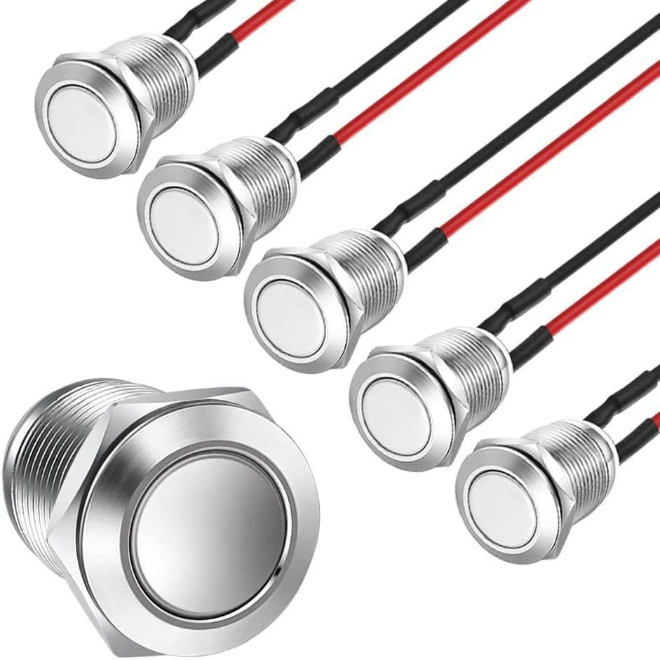
Choosing the right switch starts with understanding its pinout. This guide breaks down the metal push button switch pin definition and wiring for 2‑pin, 3‑pin, 4‑pin and 5‑pin types. For a ready-to-install, pre-wired option, explore our Metal Push Button switches with full specifications and free samples.
I. Basic Terminology (General)
COM (C) Common Terminal: Main input line for the switch, switching reference point.
NO Normally Open: Disconnected when not pressed, conducts when pressed (commonly used for start/jog).
NC Normally Closed: Conducts when not pressed, disconnects when pressed (commonly used for emergency stop/stop).
LED+ / LED-: Positive and negative terminals of the indicator light on the illuminated button. The LED must be connected in series with a current-limiting resistor (220Ω for 5V, 1kΩ for 12V, 2kΩ for 24V).
II. 2-Pin Metal Button (Pure Switch without Light)
Pin Definitions
Only 2 contacts, single-channel normally open, no COM/NC distinction; press to connect, release to disconnect.
Wiring (Jog Start)
Power + → Pin 1
Pin 2 → Load Positive
Load Negative → Power -
Applications: Device jogging, simple triggering, microcontroller button input.
III. 3-Pin Metal Button (No-LED Single-Pole Double-Throw SPDT)
Pin Standard Order (Rear View)
1 = COM Common Terminal, 2 = NC Normally Closed, 3 = NO Normally Open.
On/Off Logic
Release: COM ↔ NC On, COM ↔ NO Off.
Press: COM ↔ NO On, COM ↔ NC Off.
Two Practical Wiring Methods
Jog Start (NO Connection)
Power + → COM (1)
NO (3) → Load +
Load - → Power -
Press to Stop (NC Emergency Stop Connection)
Power + → COM (1)
NC (2) → Load +
Load - → Power -
IV. 4-Pin Metal Button (Divided into 2 Types: No Light / With Light)
Type 1: 4-Pin Metal Push Button without Light (Double Parallel Normally Open)
Internal diagonal pins are connected in parallel, functioning equivalent to a 2-pin switch. Pin 1/3 is one group, and pin 2/4 is another group. Pressing both pins simultaneously activates the switch; only one pair is needed, the other pair remains floating.
Type 2: 4-Pin Illuminated Metal Button (Most Common)
Standard Pin Definitions (Back): 2 = COM Common, 3 = NO Normally Open, 4 = LED+, 5 = LED- (Pin 2/3/4/5 in your question correspond to this model).
Wiring Scheme 1: Illumination Only When Button Is Pressed (Synchronous Indication)
Control Circuit: Power + → 2 (COM), 3 (NO) → Load +, Load – → Power -.
Illumination Circuit: 3 (NO) → Resistor → 4 (LED+), 5 (LED-) → Power -. Pressing the button: Load is active + Illumination; releasing the button disconnects all signals.
Wiring Scheme 2: Indicator Light Is Always On (Power Indication)
Control Circuit: Same as above (COM+NO controls the load).
Illumination Circuit: Power + connected to 4 (LED+) via resistor, 5 (LED-) connected to Power -. Illumination is always on when powered on, unaffected by button press.
V. 5-Pin Illuminated Metal Button (Industrial Mainstream, 2/3/4/5+1) (Complete Pin Configuration)
Standard 5-Pin Complete Definition (5 Terminals on the Back)
1 = COM Common, 2 = NC Normally Closed, 3 = NO Normally Open, 4 = LED+, 5 = LED.
4 Standard Wiring Sets
Solution 1: Jog + Press to Turn On Light (NO Control, Synchronous Indicator)
Main Circuit: Power + → 1 (COM), 3 (NO) → Load Positive, Load Negative → Power Negative.
LED Circuit: 3 (NO) → Current Limiting Resistor → 4 (LED+), 5 (LED-) → Power Negative.
Function: Press and hold to run the device, light on; release to stop and turn off the light.
Solution 2: Normally Closed Emergency Stop (NC Circuit) + Constant Light
Main Circuit: Power + → 1 (COM), 2 (NC) → Load +, Load – → Power -.
LED Circuit: Power + → Resistor → 4 (LED+), 5 (LED-) → Power -.
Function: Normal operation: Device runs, light on; press button to stop the device.
Solution 3: Constant Power Indicator (Independent LED Circuit)
LEDs are powered independently, do not follow the switch action, only indicate that the whole machine is powered on. 4 (LED+) connected to the power supply + with a series resistor; 5 (LED-) connected directly to the power supply negative terminal.
Solution 4: Self-locking Button (Press to Turn On and Then Off) Universal Wiring Method
Wiring logic is the same as the jog NO connection method, the only difference is the button’s mechanical structure, no wiring modification required.
VI. Quick Pin Identification with a Multimeter (Test All Unmarked Pins)
Switch Contacts (COM/NO/NC)
Without button pressed: The two pins that beep = COM + NC.
With button pressed: The original NC is disconnected, the two pins that beep = COM + NO.
LED Pins (Pin 4, Pin 5)
Use the multimeter in diode mode, red to pin 4, black to pin 5, dim light/voltage drop = LED positive and negative terminals; reverse connection has no effect.
VII. Safety Precautions
LEDs without built-in resistors must be connected to an external current-limiting resistor; otherwise, the LED will burn out instantly.
For controlling high-current loads (motors, solenoid valves), the button cannot be directly connected; a relay is required.
DC LEDs have positive and negative terminals; pins 4 and 5 must not be reversed; this does not apply to AC non-polarized LEDs.
Waterproof metal buttons should be soldered for ≤3 seconds; high temperatures will damage the internal seal.
Conclusion
Correctly identifying COM/NO/NC and the LED pins is the key to safe, reliable wiring. If you need a waterproof, pre-wired 12mm switch for your project, our Metal Push Button products come with clear pinouts, silver-alloy contacts and free samples.