Blog
Micro Switch Selection Process: An 8-Step Guide

Micro Switch Selection Process: An 8-Step Guide
Choosing a micro switch is rarely a single decision; it is a chain of matched choices where each step depends on the one before it. A dependable micro switch selection process follows a fixed order — clarify the need first, then match electrical, mechanical, environmental, lifespan, installation and compliance requirements before you commit to a part. This guide lays out the eight steps engineers use to turn an application brief into a validated component, cutting the risk of field failure and expensive redesign.
1. Define Application Requirements (the starting point)
Every sound selection begins with the duty profile. Confirm the control logic — normally open (NO), normally closed (NC) or single-pole double-throw (SPDT) — and the load type. Resistive loads are straightforward, but inductive loads such as motors and solenoid valves demand derating and arc suppression. Alongside that, list the real operating voltage, current, actuation frequency and the trigger method, whether a finger press, a cam, a slider or a robotic arm. It also helps to document the acceptable tolerances and the worst-case scenario, because a switch sized only for nominal conditions often fails at the edges. These numbers become the constraints for every later step.
2. Electrical Parameter Matching (first priority)
Electrical fit is the gatekeeper. The rated voltage and current must exceed the circuit values with a safety margin — roughly 1.5× is a sensible rule — and AC and DC ratings must never be mixed. Inductive loads need further derating; a switch that handles 5 A resistively may only manage a fraction of that when switching a motor. Next, choose the contact form and material: silver alloys such as AgSnO₂ suit high current, while gold-plated contacts protect low-signal and weak-current loops by keeping contact resistance low. Finally, verify the contact resistance (≤50 mΩ typical, ≤20 mΩ for precision circuits) and the contact gap for adequate breaking and withstand voltage.
3. Mechanical Parameter Matching
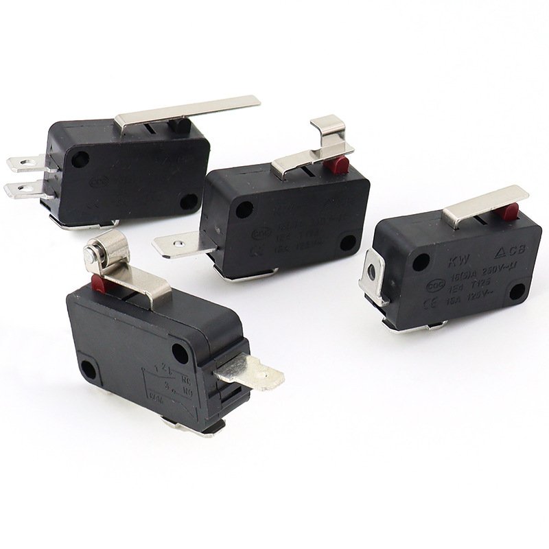
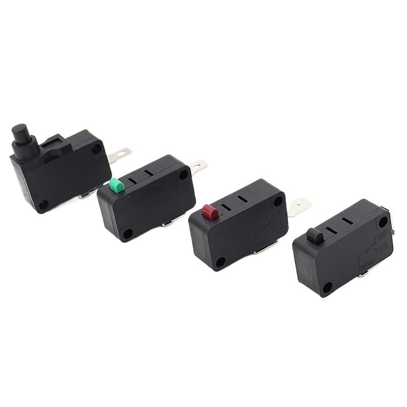
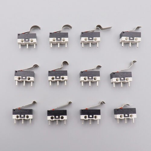
Even a perfect electrical match fails if the mechanism cannot actuate it. The operating force (OF) and return force must suit the driving assembly: the mechanism’s output should be at least 1.5× the switch’s operating force, and the return force must beat the reset resistance to avoid sticking. Travel is the second concern — pre-travel, differential travel and over-travel must all fit the actuator stroke without crushing the internal spring blade. Last, match the actuator style (plunger, roller, lever or hinge) to the trigger, eliminating any mechanical interference.
4. Environmental Adaptability Matching
The switch must survive where it lives. Check the operating temperature range — typically −25 °C to +85 °C — against the equipment: high heat stresses the housing, low cold thickens the grease and slows the return. Humidity is an easy factor to miss; persistent moisture drives contact oxidation and leakage unless the part is sealed. Choose the IP rating accordingly: IP40 for clean indoor use, IP65 for damp or dusty areas, IP67 for outdoor rain, and Ex-certified models for explosive atmospheres. Where vibration or shock is severe, pick an anti-vibration type or add cushioning; in corrosive settings, select sealed or corrosion-resistant materials.
5. Lifespan and Reliability Matching
Lifespan is where many designs fall short. The decisive metric is electrical life — the number of loaded switching cycles — not the mechanical figure. Size the margin against your actual actuation frequency; high-cycle applications should target 100k cycles or more. Spring material matters too: beryllium copper for high-frequency long life, phosphor bronze for standard duty, and stainless steel where humidity is a concern.
6. Installation and Structure Matching
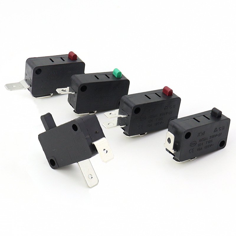
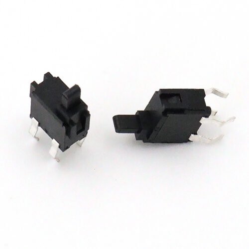
A part that cannot be mounted cleanly is the wrong part. Verify the outline dimensions and mounting holes against the space reserved in the device, watching for clearance and interference. Decide whether the body sits on a panel, snaps into a bracket, or mounts directly to a PCB, because each option changes the footprint and the assembly sequence. Then decide the terminal type — quick-connect or solder — and confirm the pinout (COM/NO/NC). Respect the specified soldering temperature and time so you do not thermally damage the internals during assembly.
7. Compliance and Certification Matching
Market access depends on the right paperwork. China calls for CCC, North America for UL, and Europe for CE or ENEC, while RoHS 2.0 and REACH cover environmental compliance. Once every performance requirement is satisfied, weigh cost against service life to land the best-value model rather than the cheapest one.
8. Prototype Validation (final confirmation)
The process closes with proof, not assumption. Before volume purchasing, run a sample test that confirms trigger reliability, endurance and environmental adaptation under the real operating conditions. A short field trial on a few units often reveals issues — a marginally stiff actuator, a borderline temperature margin — that paper specs never show. Only when the prototype passes should you release the part for production. To see certified, in-stock models that already meet these steps, you can browse our full micro switch catalog or explore the micro switch product category and shortlist candidates for your prototype build.