Blog
Valve Position Switch vs Limit Switch: Types & Maintenance

What Is a Valve Position Switch?
A valve position switch is a compact detection device mounted on an industrial control valve. It converts the valve’s fully-open or fully-closed mechanical state into a standard switching signal, then feeds that signal to the control room, DCS or ESD system for remote monitoring and interlock control. Unlike a safety cutoff device, its core job is signal feedback, not power interruption.
Valve Position Switch vs Limit Switch: The Core Difference
Both devices rely on a micro switch actuation mechanism, so they are frequently confused. The real difference lies in purpose, installation position and control logic.
| Aspect | Valve Position Switch | Limit Switch |
|---|---|---|
| Primary role | Signal feedback & remote monitoring | Safety protection & stroke cutoff |
| Circuit position | Signal loop to DCS / ESD | Series in the power circuit |
| Trigger result | Outputs valve state signal | Disconnects power at stroke limit |
| Typical install | On the control valve body | On moving parts / safety doors |
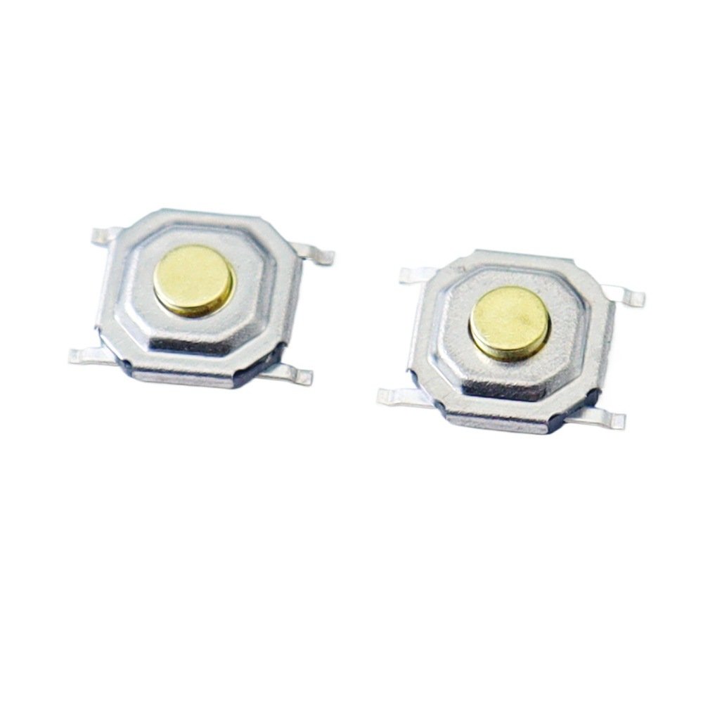
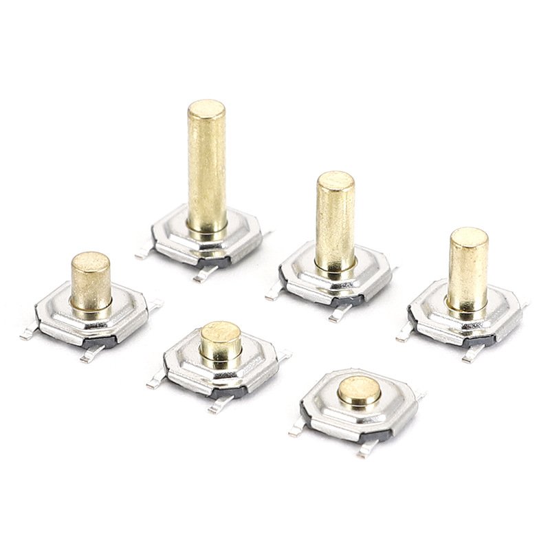
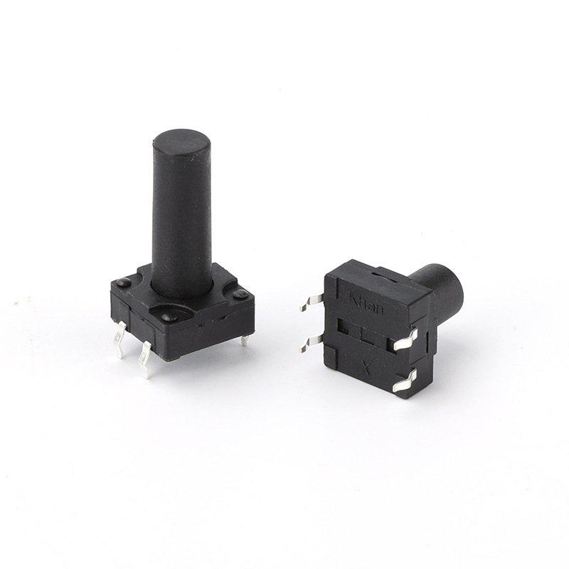
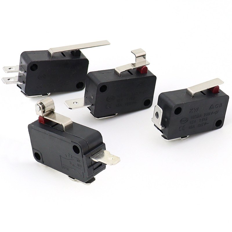
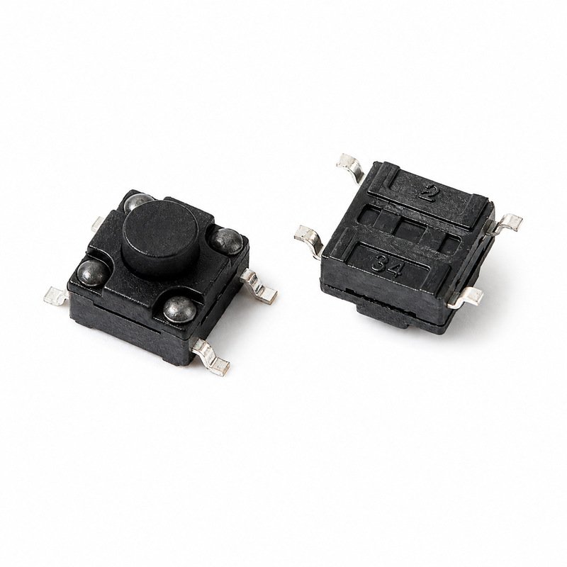
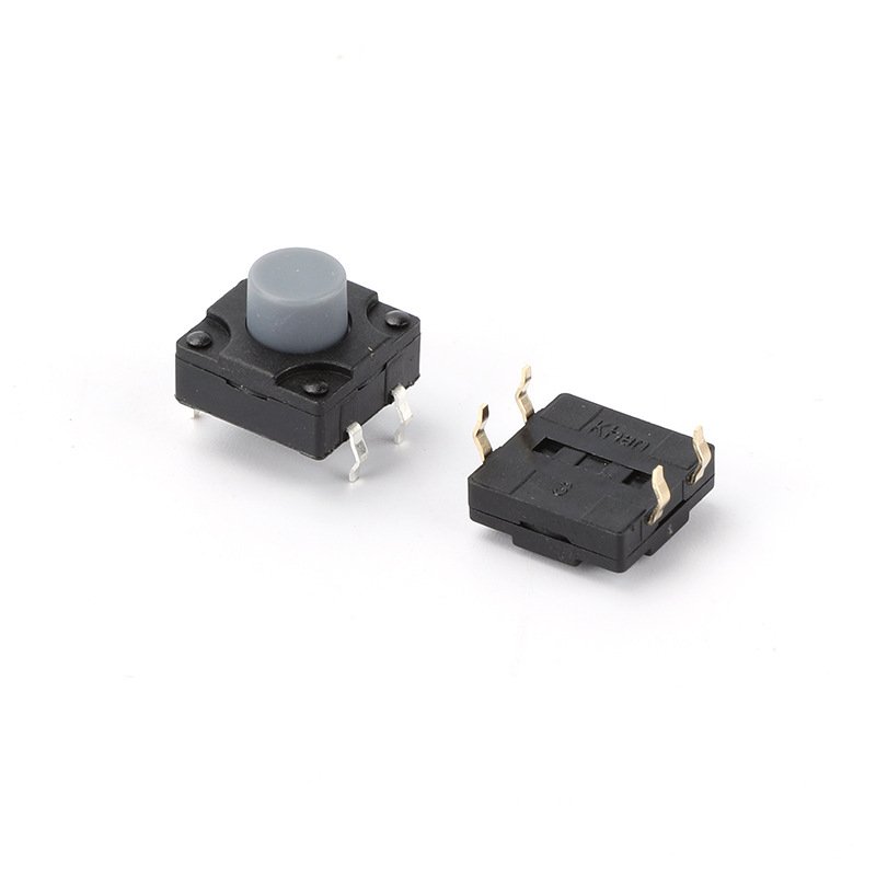
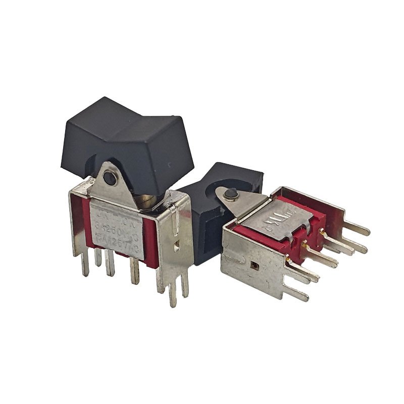
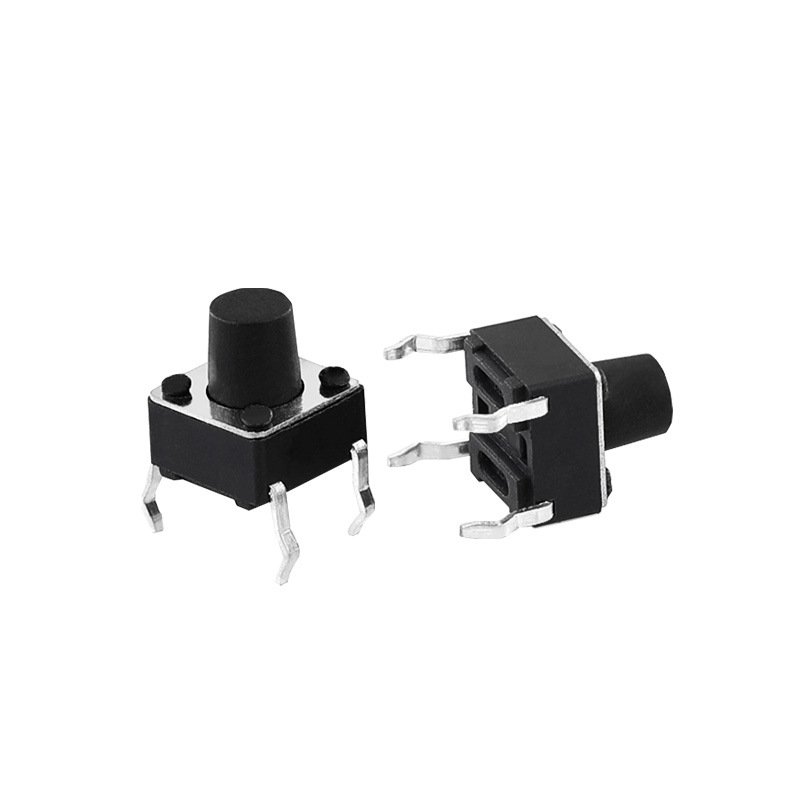
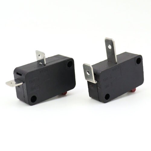
For the sensing elements behind these devices, browse our full range of micro switches for valve and limit-switch applications.
Two Main Types of Valve Position Switches
Contact-Type Valve Position Switch
The contact-type model uses a high-precision micro switch as its sensing element. A metal baffle on the valve stem strikes the actuator once the valve reaches position, toggling the internal contacts. It supports SPDT and DPDT configurations with NO or NC logic, and runs on a simple two-wire passive design that saves wiring cost.
Proximity Valve Position Switch
The proximity model is a non-contact detector using eddy-current, capacitive or inductive-bridge sensing. With no mechanical wear, it suits high-frequency valve switching and harsh environments, though its procurement and installation cost is higher than mechanical types.
Standard Daily Maintenance
- Calibrate the trigger point to the valve’s full-stroke open and closed positions.
- Identify NO / NC / common terminals to avoid wiring logic errors.
- Keep terminal insulation clean and the junction box sealed against water and dust.
- Set safety-barrier dial parameters to match NO/NC and contact or proximity mode.
- Use redundant switches for key interlock valves and test contact resistance during shutdown.
Common Faults and Troubleshooting
Vibration, corrosion and aging cause most faults. If a valve position switch drifts out of position, re-tighten the mount and recalibrate the stroke. For unstable signals, measure loop resistance with a multimeter to locate bad wiring. For false interlock trips, switch the safety barrier to the spare contact. Inspect the box seal regularly to keep steam and dust out.
Need a reliable sensing element for your build? Explore our industrial micro switches for position and limit detection.
Frequently Asked Questions
What is the main difference between a valve position switch and a limit switch?
A limit switch cuts power to restrict mechanical stroke for safety, while a valve position switch outputs valve-state signals for remote monitoring and interlock control.
What are the two types of valve position switches?
Contact-type mechanical switches and non-contact proximity switches. Contact types are low-cost and easy to install; proximity types offer higher stability for high-frequency operation.
How to maintain industrial valve position switches?
Calibrate trigger positions, check wiring insulation and box sealing, set safety-barrier parameters, test contact resistance, and add redundancy for key interlock valves.